Managing Relationships
Relationship settings pertain to the configuration options and parameters that govern the connections and interactions between various elements within the facility infrastructure. These settings play a critical role in establishing and managing relationships such as spatial dependencies, maintenance associations, and logistical connections between different assets or areas within a facility. For instance, these settings may allow users to define parent-child and child-parent relationships to represent hierarchical dependencies, create associations between equipment and specific maintenance schedules, or establish spatial connections to reflect the physical layout of facilities. The configuration of relationship settings enhances the system's ability to model and navigate complex relationships within the facility environment, enabling efficient management, maintenance planning, and strategic decision-making.
Step 1: Adding New Relationships
Establishing a relationship between modules involves creating a connection or link between them to facilitate the exchange of data. This connection enables one module to reference or interact with another, fostering seamless collaboration within a system. When creating a relationship, you typically define how the modules are related (type of connection) and the module to which the connection is to be established. This connection enhances the functionality of the modules, allowing them to work cohesively and share relevant information, ultimately optimizing the overall performance of the system.
The application allows creating the following types of relationships:
Creating a Relationship
Creating a standard relationship involves defining and configuring the relationship parameters based on the specific needs of the system, providing a straightforward and conventional way to represent connections within the given framework.
To create a new relationship,
Select the required module and navigate to the Related section. All the related modules are displayed, as shown below.
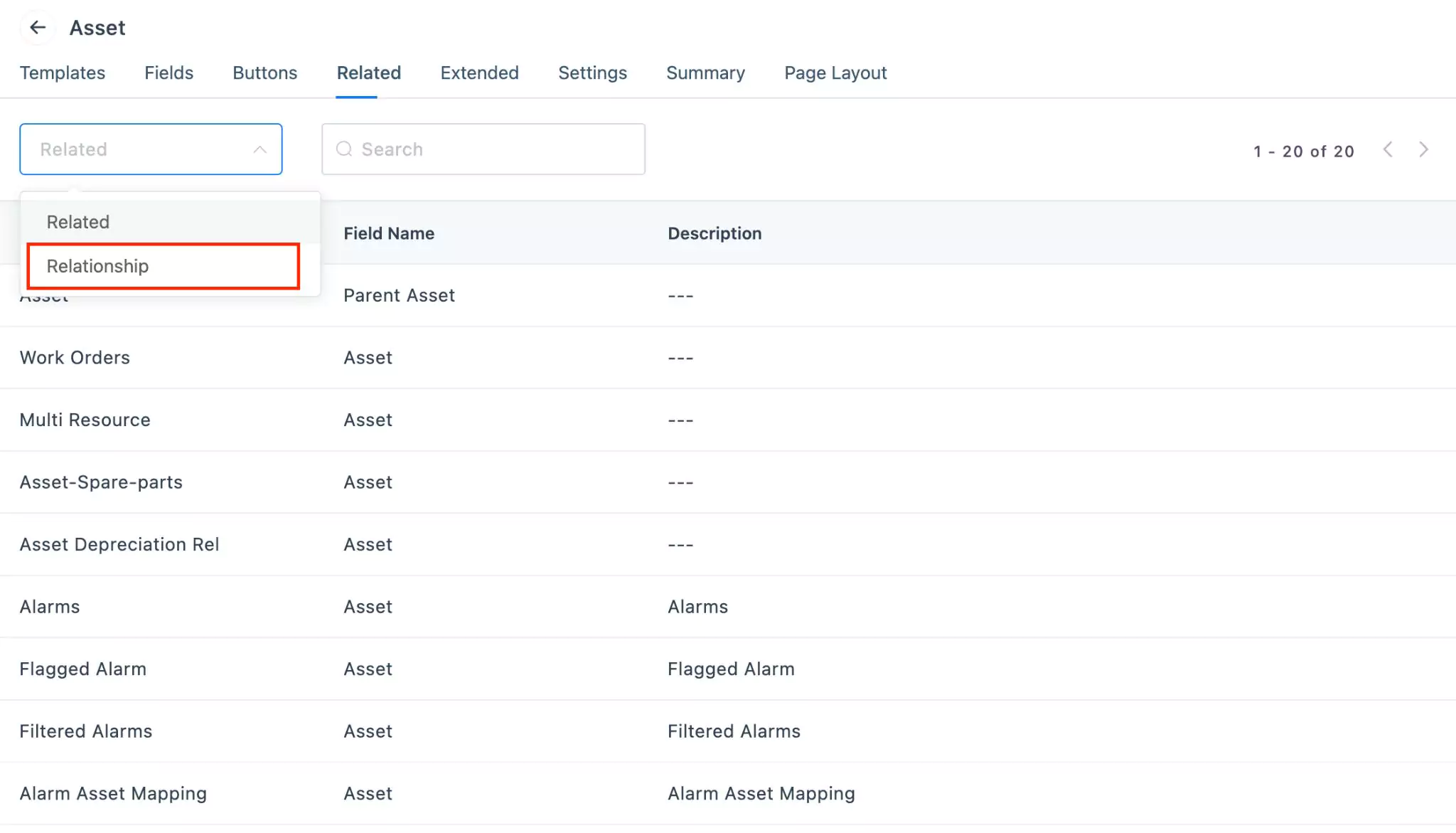
Switch to the Relationship view in the drop-down menu.
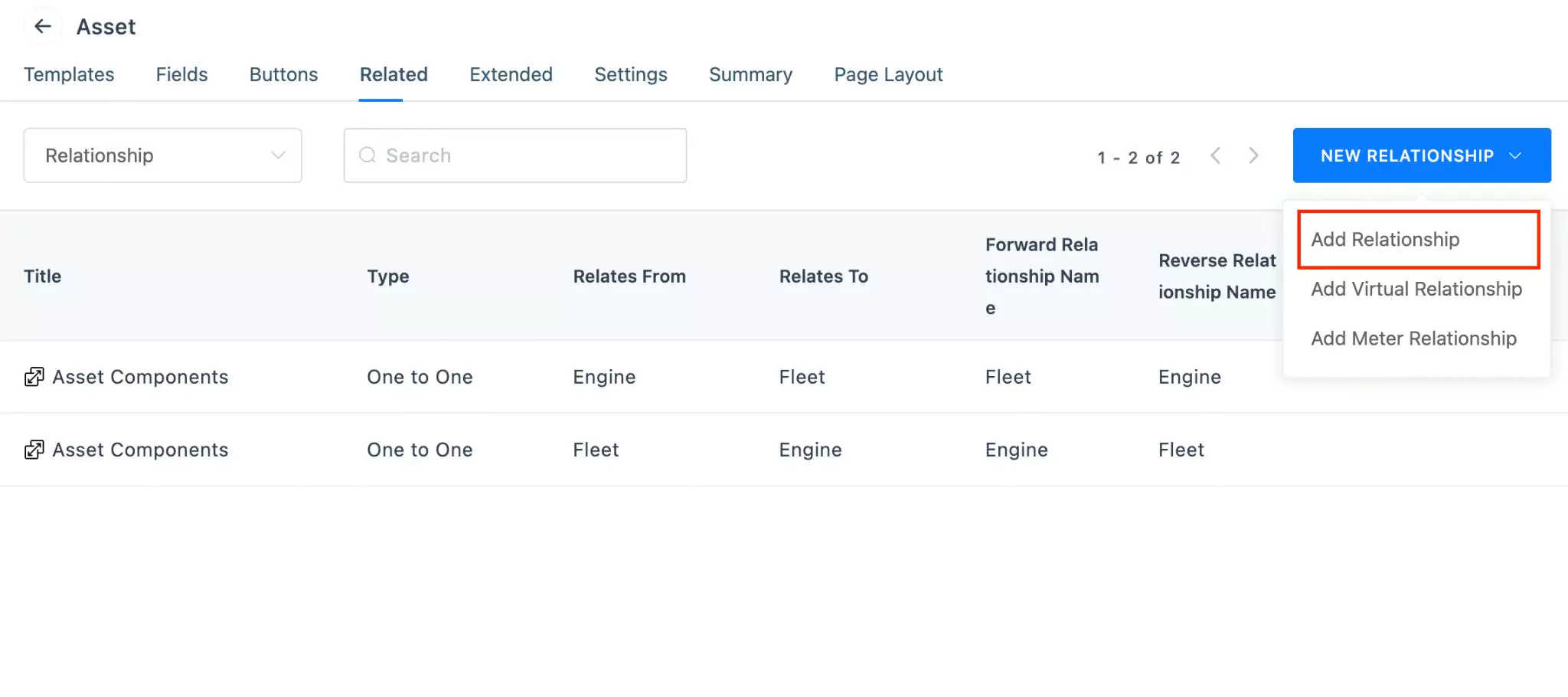
Click NEW RELATIONSHIP and select Add Relationship. The NEW RELATIONSHIP window appears, as shown below.
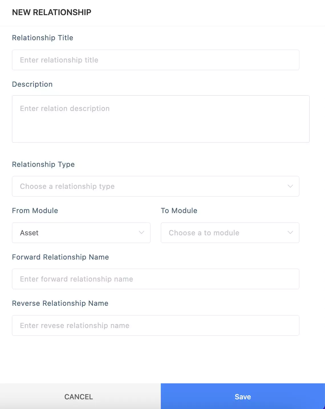
Update the required details in this screen.
Relationship Title - A label to identify the relationship
Description - A short note explaining the purpose of the relationship
Relationship Type - The classification defining how the modules are related. You can choose from the following options:
- One to One - Establishes a direct and unique connection between one record in the first module and one record in the second module. It's a straightforward and singular relationship.
- One to Many - Sets up a relationship where one record in the first module can be associated with multiple records in the second module. It's a unidirectional relationship allowing one-sided connections.
- Many to One - Similar to One to Many but in reverse. Multiple records in the first module can be associated with a single record in the second module. It's a way of expressing a hierarchy or categorization.
- Many to Many - Creates a versatile relationship where multiple records in the first module can be linked to multiple records in the second module. It establishes a flexible and bidirectional connection between modules, allowing for complex associations.
From Module - The module from which the connection is established.
Note: This field is set to the current module by default and cannot be modified.To Module - The module to which the connection is to be established.
Forward Relationship Name - The label for a relationship established from the source module to the target module.
Reverse Relationship Name - The label for a relationship established from the target module back to the source module.
Click Save. The Relationship is now successfully created.
Note: For every new relationship, two new records will be created indicating the forward and reverse relationship.
Thus the process of building relationships leads to the establishment of both parent-child and child-parent relationships between the associated modules.
Creating a Virtual Relationship
A virtual relationship takes on a dynamic role, involving the configuration of a chaining path between two distinct modules through intermediary connections. For example, to establish a virtual connection between AHU and Energy meter modules, you can configure the chaining path from AHU to Chiller and Chiller to Energy meter modules. Configuring such a relationship through virtual connections offers a more detailed understanding of the energy consumption process, dependencies between components, targeting detailed monitoring and issue resolution. Furthermore, anomalies detected in the target module can be traced back either to the preceding levels or to the source module, aiding in efficient troubleshooting.
To build a virtual relationship,
Click NEW RELATIONSHIP and select Add Virtual Relationship. The New Virtual Relationship window appears, as shown below.
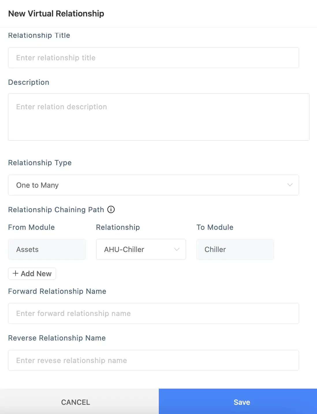
Update the Relationship Title, Description, Relationship Type, Forward Relationship Name, and Reverse Relationship Name, as explained in the Creating a Relationship section.
Configure the Relationship Chaining Path.
Select the relationship from the drop-down that connects to the required intermediate module.
Note: The source module remains unchanged and it is set to the current module by default. The relationships displayed in the dropdown are the ones that correspond to the selected relationship type. All the one-to-one relationships are always displayed irrespective of the chosen relationship type, as they underlie within any relationship type.Click the Add New link. Select the relationship that connects the previous target module and the next module in the chain.
Note: The source module remains unchanged and it is set to the target module in the preceding relationship.
The application allows you to build the chaining path, incorporating multiple relationships between the source and the target module. You can use the icon corresponding to a relationship to remove it.
Click SAVE. The virtual relationship is now successfully saved and can be applied similarly to other relationships.
Creating a Meter Relationship
Meter relationship refers to the connections or associations established among different meters. Meters are devices used to measure and monitor various aspects such as energy consumption, water usage, or other utility metrics.
Creating relationships among meters allows for a structured representation of how these meters are interconnected or influence one another. This can include dependencies, hierarchies, or associations that provide a more comprehensive understanding of the data collected by each meter.
For example, a meter relationship might signify that one meter is a sub-meter of another, representing a hierarchical structure where the sub-meter contributes to the data collected by the main meter. Understanding these relationships is crucial for accurate data analysis, energy management, and identifying dependencies within the monitored systems.
You can use the Add Meter Relationship option in the Relationships view to create a new meter relationship. It's important to note that either the "from" or "to" module must be meters or their extended modules. The meter relationship configuration allows for connections either from meters or meter extended modules to other modules, or vice versa. Read the Creating a Relationship section for the detailed procedure to configure the relationship.
In the Relationship screen list view, the various types of relationships are distinguished by their corresponding icons.
Step 2: Including in Page Layout
To activate the relationship created you must ensure to include it in the Relationship section as a part of the page layout configuration. You can simply drag and drop the required relationship into the Relationship section, as shown below.
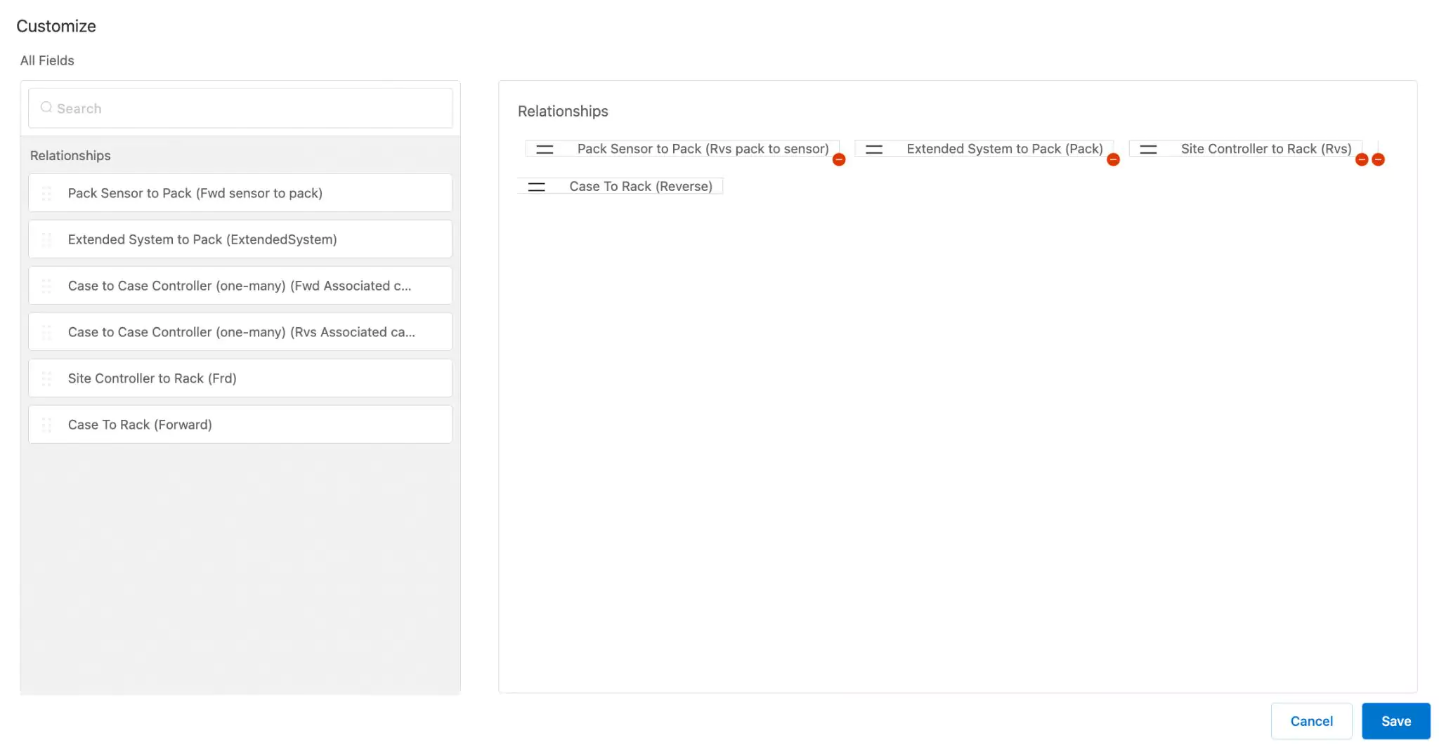
Read the Customizing Summary/Related Page Layout section for more information.
Step 3: Associating Components
After establishing a relationship, it is essential to define the components between which the relationship should exist. For instance, let's consider creating a one-to-many relationship from a Chiller to AHU, indicating that a chiller is connected to multiple AHU units in an organization. In this context, it becomes necessary to specify which chiller unit is linked to which AHU units. It's important to note that, in this scenario, a many-to-one relationship is automatically established between the AHUs and the chiller. Read the Associating Relationship Components section in Asset Management feature to understand how to associate components and establish a valid relationship.
Step 4: Utilizing Relationships
The application of relationships plays a crucial role in enhancing the understanding and management of complex systems.
In the realm of Analytics, relationships enable a more comprehensive assessment of performance metrics. By establishing connections between various data points, systems, or processes, organizations can gain insights into the interdependencies that influence overall performance. This aids in identifying areas for improvement, optimizing workflows, and making data-driven decisions to enhance operational efficiency.
In diagnosing the alarming conditions, relationships are instrumental in modeling and analyzing the connections between different components within a facility. This can include dependencies between equipment, spatial relationships, or operational dependencies. Understanding these relationships is vital for effective maintenance planning, energy optimization, and ensuring the smooth functioning of facility assets.
Integrating relationships into the processes like formulating an alarm condition or performing a Key Performance Indicator (KPI) calculation serves as a powerful tool for understanding, optimizing, and deriving meaningful insights from complex systems and datasets. Let's consider defining an alarm rule that incorporates a relationship. Typically, when configuring the alarm condition, you need to define variables (e.g., A, B, ...) and then create an expression (e.g., A == 1) involving these variables to identify inconsistencies. The application offers the flexibility to create related groups, which can be treated as variables for building expressions. These related groups can be configured based on the relationships created for the selected asset category. Read the Configuring Alarm Rule Settings section in the Diagnostics module to understand how to configure an alarm rule.